How The Charging System Work
The car's battery operates on the principle that if two dissimilar metal plates, wired in a circuit, are immersed in an acidic liquid solution (an electrolyte), a chemical reaction takes place which is accompanied by a flow of electric current. If this reaction were allowed to continue, an equilibrium point would be reached at which no further chemical reaction takes place (ie no electricity is produced) and the cell is discharged.
With some metals there is no way of reversing the status to restore the discharged cell to its charged condition and, in such a case (referred to as a primary cell battery), the cell would require replacement every time it was discharged. The lead-acid car battery, however, contains a combination of metals which makes it possible to discharge the battery and then, by the simple expedient of passing current through it in the opposite direction, recharge it - thus restoring the battery to the state where electricity can once again be produced by chemical means (secondary cell battery).The battery is recharged by a dynamo - a device which converts mechanical energy into electrical energy by means of magnetic induction.
Generators
On older cars a generator recharged the battery. However, on modern cars an alternator is used for this purpose. In a generator, two permanent magnets with opposite poles are mounted 1800 from each other on the inside of the generator casing. A constant but weak magnetic field thus exists between these magnets and, when the armature is rotated in this field, its windings cut the magnetic lines of force. This induces a weak flow of current in the windings of the armature. The current is fed through one of the carbon brushes on the armature commutator and flows from the armature terminal on the generator towards the regulator. In order to strengthen the magnetic field in which the armature rotates -thereby increasing the output of the generator - the armature circuit is tapped from the armature brush on the commutator. This allows some of the generator current to flow through the field windings which are wound around the permanent magnets, thereby boosting the constant magnetic field by electromagnetic means.
This circuit emerges from the generator via the field terminal and is earthed via various resistances and a relay inside the regulator. Depending on the type of generator used, the shunt or field winding could be taken from a connection on the regulator to the field terminal on the generator and then earthed in the casing of the generator after passing through the field windings.
Alternators
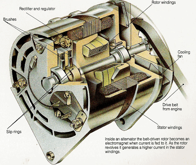
In an alternator there are no permanent magnets to provide the magnetic field which is why a car fitted with an alternator and which has a flat battery, cannot be push-started. Rather, a magnetic field is induced when the engine is switched on - ie the battery provides current for an electromagnetic field. Furthermore, whereas in a generator the field windings are stationary, those in an alternator rotate (rotor windings) and the armature windings are fixed (stator winding). In this way, the rotor becomes an electromagnet supplied with a small amount of electricity from the battery through carbon or copper-core brushes (contacts) that touch two rotating metal slip rings on its shaft. The rotation of the electromagnet induces a much larger current in the stator windings. This alternating current changes its direction back and forth every time the rotor turns, and has to be turned into a one-way flow by a diode bridge in-side the alternator.
A generator, on the other hand, produces direct current by virtue of its commutator and is less efficient. In addition, the power density (ie the ratio of the electrical power produced to mass)of an alternator is much higher than that of a generator. Regulating the current to the battery The current from an alternator is rectified into direct current by a set of diodes that allow current to flow through them in one direction only. To charge the battery, the voltage supplied to it must be neither too low nor too high. The alternator has a transistor operated control device that regulates the voltage by supplying either more or less current, as required, to the electromagnet.
The rectifier and regulator are usually inside the alternator housing, but on some alternators they are outside it, mounted on the alternator body. A generator does not need a rectifier -here is a voltage regulator in a separate box which has relays. One relay controls he voltage level by briefly cutting off the current in the field coils; the second prevents the generator from overcharging and damaging the battery; the third relay stops he battery discharging when the generator is turning too slowly to charge it.
Testing an alternator
and checking its output
Alternators have replaced
generators as dynamos
on modern cars; they are
capable of producing more
current. Any short or open
circuit or incorrect
connection can cause a
sudden surge of voltage that
will damage electronic parts.
Never, therefore, make or
break any connection while
the engine is running.
Checking alternator output
using an.amp meter in series
with the charging system
should be done only after the
Connections have been made
with the engine stationary. A
safe test can be made with an
induction ammeter held parallel
to the output cable, but it is less reliable.
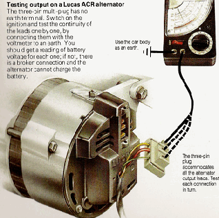
Testing output on a Lucas ACR alternator
The three-pin multi-plug has no earth terminal.
Switch on the ignition and test the continuity of
the leads one by one, by connecting them with
The volt meter to an earth. You should get a
reading of battery voltage for each one; if not,
There is a broken connection and the
alternator cannot charge the
Battery.
Checking the alternator output leads
Check that all connections are secure. Start
the engine and connect a voltmeter or tester
across the battery terminals. Have a helper
rev up the engine from idling speed. If the
voltage does not rise (or the tester lamp or
headlamps do not brighten) as engine speed
increases, the alternator output is either too
low or not reaching the battery. Check that the
Alternator is actually turning. Switch off the
engine and check the tension on the drive
belt. Check that wiring to the alternator is not
broken or disconnected.If these checks do not
reveal a fault, disconnect the battery earth terminal
and check the alternator leads with a voltmeter.
There is one thick output cable from the alternator
to the starter solenoid, and a smaller lead or leads.
Some or all of the leads may be connected by a
multi-plug. If the heavy lead to the starter is separate
(ie not on a multi-plug), you do not have to disconnect it,
and you can test it any time the battery is connected,
using a test lamp. It should be permanently live.
Disconnect the smaller leads and/or the multi-plug.
If the alternator has an external voltage regulator,
there will be separate connections to it; do not undo
these connections, even if you have to unfasten the
regulator and move it aside. Reconnect the earth
terminal on the battery and switch on the ignition.
Test the alternator leads by connecting each in turn
with the voltmeter to an earth. If there are any leaks
which fit onto terminals marked with an earth symbol
or E, N, -, or D, do not test them. They are earth connections.
All the positive leads should give readings of battery voltage. If there is a small lead marked 'Ind' for the ignition warning light, and it alone remains dead when the ignition is switched on, the light may have blown. If any other wire which ought to be live is not, check it for a loose connection or for a breakage or faulty insulation causing a short circuit. If all the wires are live and there is still a fault in the charging system, it is probably in the alternator or the regulator. Take the car to an auto-electrician. Disconnect the earth terminal on the battery before reconnecting all the leads.
Nowadays it is important to test alternators with a scope, this will enable you to see what the ac diode pattern is, if the ac voltage is to high then the alternator needs repairs. To see a good scope diode pattern, please visit this page.
With some metals there is no way of reversing the status to restore the discharged cell to its charged condition and, in such a case (referred to as a primary cell battery), the cell would require replacement every time it was discharged. The lead-acid car battery, however, contains a combination of metals which makes it possible to discharge the battery and then, by the simple expedient of passing current through it in the opposite direction, recharge it - thus restoring the battery to the state where electricity can once again be produced by chemical means (secondary cell battery).The battery is recharged by a dynamo - a device which converts mechanical energy into electrical energy by means of magnetic induction.
Generators
On older cars a generator recharged the battery. However, on modern cars an alternator is used for this purpose. In a generator, two permanent magnets with opposite poles are mounted 1800 from each other on the inside of the generator casing. A constant but weak magnetic field thus exists between these magnets and, when the armature is rotated in this field, its windings cut the magnetic lines of force. This induces a weak flow of current in the windings of the armature. The current is fed through one of the carbon brushes on the armature commutator and flows from the armature terminal on the generator towards the regulator. In order to strengthen the magnetic field in which the armature rotates -thereby increasing the output of the generator - the armature circuit is tapped from the armature brush on the commutator. This allows some of the generator current to flow through the field windings which are wound around the permanent magnets, thereby boosting the constant magnetic field by electromagnetic means.
This circuit emerges from the generator via the field terminal and is earthed via various resistances and a relay inside the regulator. Depending on the type of generator used, the shunt or field winding could be taken from a connection on the regulator to the field terminal on the generator and then earthed in the casing of the generator after passing through the field windings.
Alternators
In an alternator there are no permanent magnets to provide the magnetic field which is why a car fitted with an alternator and which has a flat battery, cannot be push-started. Rather, a magnetic field is induced when the engine is switched on - ie the battery provides current for an electromagnetic field. Furthermore, whereas in a generator the field windings are stationary, those in an alternator rotate (rotor windings) and the armature windings are fixed (stator winding). In this way, the rotor becomes an electromagnet supplied with a small amount of electricity from the battery through carbon or copper-core brushes (contacts) that touch two rotating metal slip rings on its shaft. The rotation of the electromagnet induces a much larger current in the stator windings. This alternating current changes its direction back and forth every time the rotor turns, and has to be turned into a one-way flow by a diode bridge in-side the alternator.
A generator, on the other hand, produces direct current by virtue of its commutator and is less efficient. In addition, the power density (ie the ratio of the electrical power produced to mass)of an alternator is much higher than that of a generator. Regulating the current to the battery The current from an alternator is rectified into direct current by a set of diodes that allow current to flow through them in one direction only. To charge the battery, the voltage supplied to it must be neither too low nor too high. The alternator has a transistor operated control device that regulates the voltage by supplying either more or less current, as required, to the electromagnet.
The rectifier and regulator are usually inside the alternator housing, but on some alternators they are outside it, mounted on the alternator body. A generator does not need a rectifier -here is a voltage regulator in a separate box which has relays. One relay controls he voltage level by briefly cutting off the current in the field coils; the second prevents the generator from overcharging and damaging the battery; the third relay stops he battery discharging when the generator is turning too slowly to charge it.
Testing an alternator
and checking its output
Alternators have replaced
generators as dynamos
on modern cars; they are
capable of producing more
current. Any short or open
circuit or incorrect
connection can cause a
sudden surge of voltage that
will damage electronic parts.
Never, therefore, make or
break any connection while
the engine is running.
Checking alternator output
using an.amp meter in series
with the charging system
should be done only after the
Connections have been made
with the engine stationary. A
safe test can be made with an
induction ammeter held parallel
to the output cable, but it is less reliable.
Testing output on a Lucas ACR alternator
The three-pin multi-plug has no earth terminal.
Switch on the ignition and test the continuity of
the leads one by one, by connecting them with
The volt meter to an earth. You should get a
reading of battery voltage for each one; if not,
There is a broken connection and the
alternator cannot charge the
Battery.
Checking the alternator output leads
Check that all connections are secure. Start
the engine and connect a voltmeter or tester
across the battery terminals. Have a helper
rev up the engine from idling speed. If the
voltage does not rise (or the tester lamp or
headlamps do not brighten) as engine speed
increases, the alternator output is either too
low or not reaching the battery. Check that the
Alternator is actually turning. Switch off the
engine and check the tension on the drive
belt. Check that wiring to the alternator is not
broken or disconnected.If these checks do not
reveal a fault, disconnect the battery earth terminal
and check the alternator leads with a voltmeter.
There is one thick output cable from the alternator
to the starter solenoid, and a smaller lead or leads.
Some or all of the leads may be connected by a
multi-plug. If the heavy lead to the starter is separate
(ie not on a multi-plug), you do not have to disconnect it,
and you can test it any time the battery is connected,
using a test lamp. It should be permanently live.
Disconnect the smaller leads and/or the multi-plug.
If the alternator has an external voltage regulator,
there will be separate connections to it; do not undo
these connections, even if you have to unfasten the
regulator and move it aside. Reconnect the earth
terminal on the battery and switch on the ignition.
Test the alternator leads by connecting each in turn
with the voltmeter to an earth. If there are any leaks
which fit onto terminals marked with an earth symbol
or E, N, -, or D, do not test them. They are earth connections.
All the positive leads should give readings of battery voltage. If there is a small lead marked 'Ind' for the ignition warning light, and it alone remains dead when the ignition is switched on, the light may have blown. If any other wire which ought to be live is not, check it for a loose connection or for a breakage or faulty insulation causing a short circuit. If all the wires are live and there is still a fault in the charging system, it is probably in the alternator or the regulator. Take the car to an auto-electrician. Disconnect the earth terminal on the battery before reconnecting all the leads.
Nowadays it is important to test alternators with a scope, this will enable you to see what the ac diode pattern is, if the ac voltage is to high then the alternator needs repairs. To see a good scope diode pattern, please visit this page.

Gratis Diens Kwotasie

